|
Defining the Study Area
The second step during the investigation process is to define the study area, which is comprised of one or more areas of interest (AOI). By default each site represents a single area of interest boundary. That is, each segment or ramp are buffered by 20 ft to create an AOI boundary around the road centerline, while intersections are represented by their area of influence polygon. Only those crashes whose location falls within an AOI are used in the investigation. When the user is done defining the study area, click the NEXT > button in the lower right corner to advance to the next step.
As stated in the "Yellow Book"...
The study area typically includes the project area and should extend between 0.1 and 0.3 miles beyond the project limits for segments. For intersections, the intersection boundaries already include an area of influence, but it is possible to add the adjacent segment(s) if desired.
It should be noted that an AOI must be a closed boundary, therefore some graphics or features that are used (points and lines) will be required to be buffered to result in a boundary.
The image below shows the "Investigation Study Area" panel that is displayed on the left side of the application.
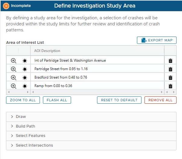
Defining Area of Interests
If the user wishes to customize the study area by modifying AOIs, there are several methods that can be used:
•Drawing a Graphic – Draw on the map using points, lines, or polygons
•Build Path – Build a path along a roadway (from/to locations)
•Select Feature – Select a feature from another reference layer
•Select Intersections – The 'Area of Influence' polygon for a selected intersection is used to define the AOI
Each AOI that is added to the query is listed in the “Areas of Interest List” grid at the top of the panel
Drawing an Area of Interest
An AOI can be drawn on the map using points, lines, or polygons that can be added to the map or traced onto it; these shapes can be optionally buffered.
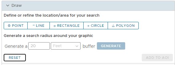
To define an AOI by drawing a graphic:
•Click the Draw tool to be used (Point, Line, Rectangle, Circle, Polygon)
•The draw tool is activated on the map. Draw the graphic on the map display (the ADD TO AOI button will then become active)
•Click the ADD TO AOI button. The graphic is added to the AOI grid (at the top)
Buffer
•To generate a buffer around the graphic, enter the specified distance, select the desired distance unit (Feet, Miles) and click the Generate Buffer button
**Note: For a point or line, the graphic must be buffered to result in a boundary. For all other graphics, generating a buffer is optional.
Resetting the Tool
•The drawing can be cleared and reset by clicking the RESET button at anytime during the operation (starts over)
Build Path
This option allows a user to build one or more paths along a route, by defining to/from locations.
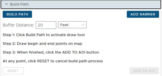
To define an AOI by building a path:
•Click the Build Path button
•Define the origin and destination of the path by clicking two points on the map.
•The path is generated between the two points and is buffered by the default distance
•Optionally, click the Add Barrier button to add barriers along the path (to recalculate the path avoiding the barrier(s)
•Click the ADD TO AOI button. The buffered path is added to the AOI grid at the top of the panel.
Buffer
•The buffer distance for the path can be changed by entering a new distance and units prior to building a path
Resetting the Tool
•The path can be cleared and reset by clicking the RESET button at anytime during the operation (starts over)
Select Feature
A user may be interested in using a feature from an existing layer to define the AOI. Different layers require different selection details. The image below shows the Select County dialog.
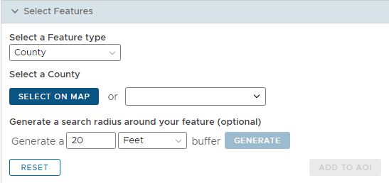
The layers from which a feature can be selected are:
•County
•Municipality
•Street
•Intersecting Street
To define an AOI by selecting features:
•Select the feature type from the picklist. Features to be selected include:
•Each dialog is slightly different. Most have an option of “Select on Map” or a picklist
•To select on map, click the button then click on the desired feature in the map display
•The selected feature can be buffered by clicking the Generate Buffer button
•Click the ADD TO AOI button. The feature is added to the AOI grid at the top of the panel.
Note: For a line feature such as Street the feature must be buffered to result in a boundary. For polygon features, such as County or Municipality, generating a buffer is optional.
Selecting Intersections
A user can select one or more intersections from the master intersection dataset using this option. The 'Area of Influence' polygon for each intersection is used to define the AOI in this case. One or more intersections may be selected.
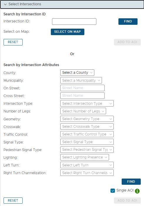
To select intersection, there are three options:
•Select by Intersection ID
•Select on the Map
•Select by Intersection Attributes
Note: When searching by attribute the “Single AOI” checkbox will define if multiple intersections will be added as a single or multiple AOIs
More specific instructions are as follows:
To select by Intersection ID
•Enter the correctly-formatted ID and select the FIND button, which will become active and selectable after entering the ID in the textbox shown below.
•If found the intersection will be displayed on the map. At that point, the ADD TO AOI button is selectableselect it to add the selected rows to the AOI.
•The 'Current Areas of Interest (AOI)' grid at the top of the "Define Investigation Study Area" panel will be populated with the AOI derived from that intersection's area of influence.
To select from the Map
•Click the SELECT ON MAP button and select an intersection on the map, navigating as necessary using the map tools.
•Any selected intersection(s) will appear on the 'Intersection Search Results'. Select the row(s) by selecting the checkbox for that row on the far-left of the mentioned grid. At that point, the ADD TO AOI button is selectable, select it to add the selected rows to the AOI.
•The Areas of Interest (AOI) grid at the top of the panel will be populated with the AOI derived from that intersection's area of influence.
To select by Intersection Attributes
•A user should select sufficient Intersection Attributes to identify the relevant intersections. If more than 100 intersections can be returned then the user will be notified of this issue, and attributes must be added to limit the results to less than 100 intersections. Intersection Attributes include the following:
oCounty
oMunicipality
oOn Street
oCross Street
oIntersection Type
oNumber of Legs
oGeometry
oCrosswalk
oTraffic Control
oSignal Type
oPedestrian Signal Type
oLighting
oLeft Turn
oRight Turn Channelization
•Any selected intersection(s) will appear on the 'Intersection Search Results'. Select the row(s) by selecting the checkbox for that row on the far-left of the mentioned grid. At that point, the ADD TO AOI button is selectable, select it to add the selected rows to the AOI. Before adding to the AOI, the 'Single AOI' checkbox can be unchecked to add each intersection selected as a separate AOI - otherwise they are added as a single AOI.
•The Areas of Interest (AOI) grid at the top of the "Define Investigation Study Area" panel will be populated with the AOI derived from that intersection's area of influence.
Manually Modifying AOI Boundaries with the Map Display
The boundary (polygon) of any AOI can be modified/edited using the interactive map display. To edit the boundary for an AOI, from the AOI Grid, click the "Zoom To AOI" (Magnifier icon) button for the specific AOI. The map display then zooms to the AOI boundary/polygon. To edit the AOI boundary, click the mouse TWICE inside the boundary, and the polygon should change to show the points that define its boundary. More specifically, each "major" point (vertex) that defines the boundary are displayed as blue dots, while "break" points (mid-point between each vertex) are displayed as gray dots.
To reshape the boundary, the user can use any of the following methods:
•To move a vertex - Hover the mouse over a blue dot (wait until it highlights by slightly expanding in size) then press/hold the mouse and drag the vertex point to the desired new location;
•To move a break point - Press/hold the mouse on a gray "break point" and wait a split second, then drag the break point to the desired new location. Note: When a gray break point is moved, it becomes a vertex (blue dot), and 2 new gray break points are created on either side at the mid point between itself and the neighboring vertices's (blue dot).
•To DELETE a vertex point (blue dot), right click the mouse on the point to be deleted, and the point is removed, collapsing/simplifying the boundary.
When done editing, click the mouse anywhere outside of the AOI boundary to accept the edits
Note: Be careful not to accidentally drag the entire polygon instead of reshaping a point along the boundary. Zoom in close enough to be sure you are on top of the point to be reshaped.
To move the ENTIRE AOI boundary
•To drag the ENTIRE AOI boundary/polygon in a given direction, press and hold the mouse anywhere inside the polygon and drag in the desired direction, releasing the mouse button at the desired location. When the mouse button is released, the boundary will be saved at that location.
Note: To undo a move of the entire AOI, press Ctrl+Z and the AOI boundary will be returned to the previous location
Managing the AOI List
Each site that was added to the investigation is represented by an area of interest (AOI) boundary and is listed in a grid that appears at the top of the Study Area panel on the left side. A number of controls/tools are available to manage the AOIs within the list. Each tool/function is described below.
Zooming to an AOI
Clicking the Zoom button (magnifier icon) on the left side of the grid zooms the map display to the location of the AOI
Flashing an AOI
Clicking the Flash button (black star icon) on the left side of the grid flashes the AOI on the map display
Deleting an AOI from the Investigation
Clicking the Delete button (trash can icon) on the right side of the grid deletes/removes the AOI from the investigation site list
Zooming to all AOIs
Clicking the ZOOM TO ALL button located BELOW the site grid zooms the map display to the location of ALL AOI in the grid
Flashing all AOIs
Clicking the FLASH ALL button located BELOW the site grid flashes ALL sites in the grid on the map display
Exporting the Map
Clicking the EXPORT MAP button at the top of the AOI grid will export the map display to a PDF file
Resetting the Study Area to Default
If adjustments have been made to the initial/default areas of interest that define the study area, the study area can be reset back to the default AOIs. To reset the study area to the default (i.e., the original AOIs associated with the selected sites from Step 1), the user can click the RESET TO DEFAULT button located under the AOI grid.
Removing All AOI's
To remove ALL AOI boundaries from the investigation, click the REMOVE ALL button under the AOI grid.
|