|
Creating a New Network Screening Scenario
To create a new network screening scenario, click the Planning>Screening>Network menu, which displays the Network Screening page as shown in the image below.

Within the top panel (above the scenarios grid), enter a scenario name and an optional description of the scenario in the text boxes provided, and click the green START button.
The scenario is initialized, and the Network Screening wizard is displayed beginning with Step 1 (Establish Focus). The scenario name is displayed at the bottom of the page as shown in the image below.
Establish Focus
This first step allows the user to define the focus of the screening by selecting specific crash severities and crash types. Simply check/uncheck the severities and crash types desired, then click the NEXT > button in the lower right corner to advance to the next step in the process.
.png)
Identify Network
The next step is to identify the network to be screened. A screenshot of this step is shown below.
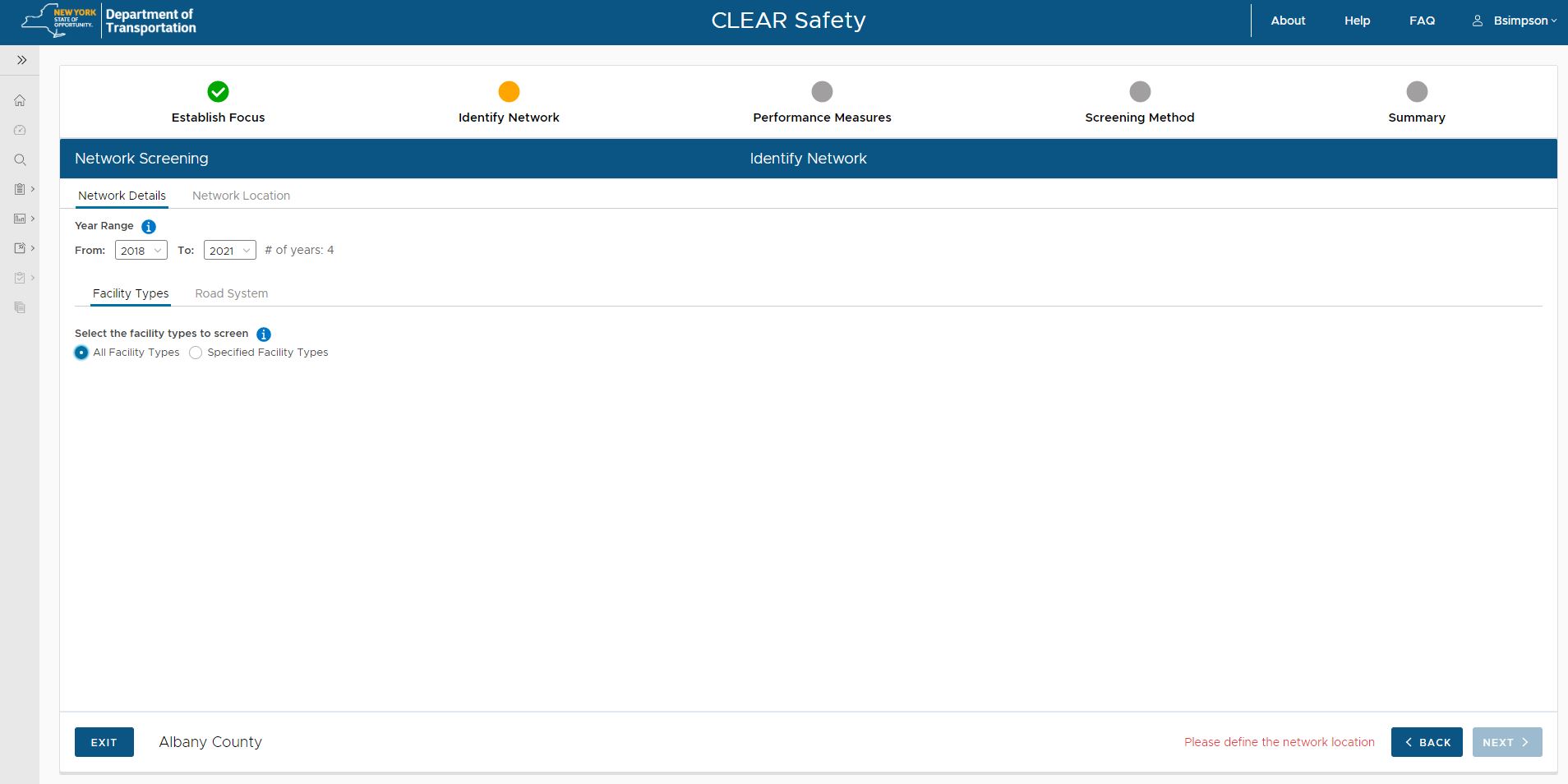
Network Details Tab
There are two tabs of information to complete in this step. The first tab is "Network Details" which allows you to specify the range of years to be included, as well as the facility types and road system to be screened.
Year Range
First, use the pick lists to select the From and To years for the year range if the default range is not desired.
Facility Types
Below the Year Range are two sub-tabs, the first of which is "Facility Types" which allows the user to specify the facility types to be screened. If all facility types are desired (default), the user can leave the default setting. However, if the user wishes to screen only specific facility types, click the radio button for "Specified Facility Types" which will display a list of facility types for Segments, Intersections and Ramps as shown in the image below.
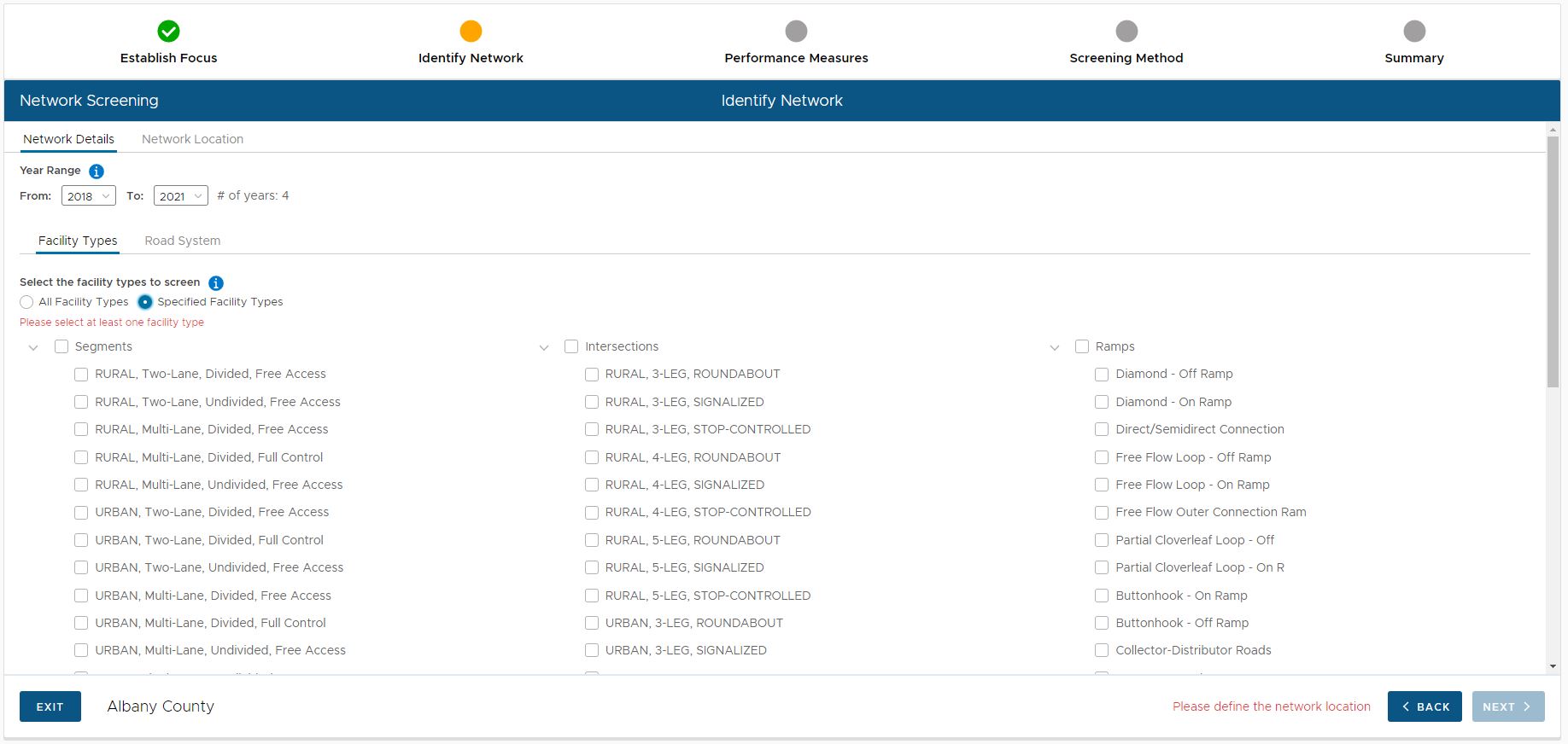
Next, check at least one facility type if specifying types in this manner.
Road System
Once the year range and facility types are selected, click the "Road System" sub-tab which allows the user to specify the jurisdictions of roads to be screened. A screenshot is illustrated below.
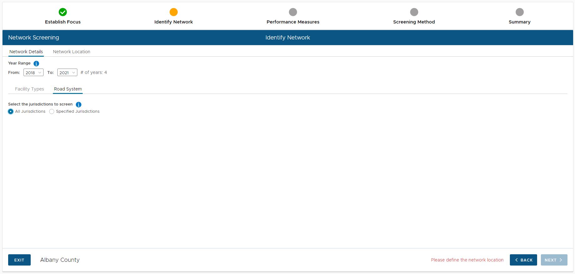
The default is to screen "All Jurisdictions" of roads. However, if the user wishes to only screen specific jurisdictions, click the radio button for "Specified Jurisdictions" which will display a breakdown of Federal, State and Local jurisdiction types from which to choose as shown in the image below.
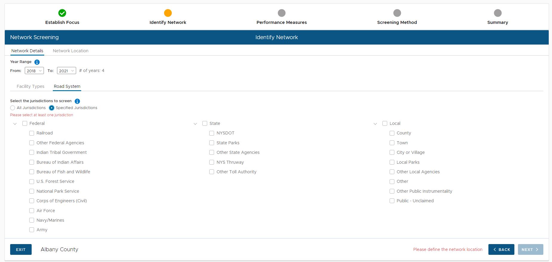
To select specific jurisdictions, check one or more jurisdictions.
Network Location
When done completing the information required on the "Network Details" tab, click the "Network Location" tab. This tab allows the user to specify the exact geography to be screened as shown in the image below.
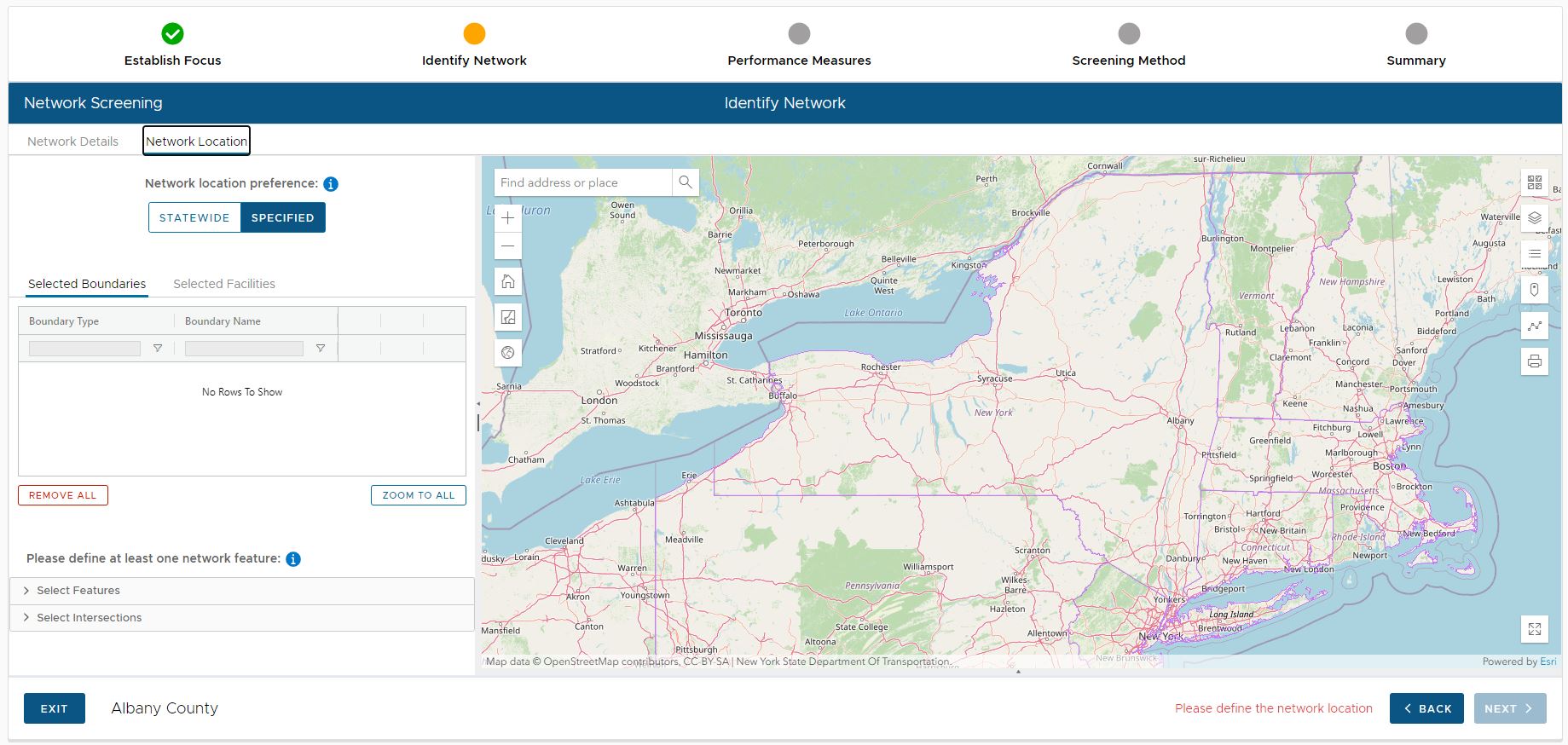
There are two accordion panels containing functionality to specify the boundary of an area to be screened: Select Feature and Select Intersection. Both are discussed in the sub-sections below.
Select Feature
The user can select a feature from an existing layer to define the area to be screened. Different layers require different selection details. The image below shows the Select County dialog.
.png)
The layers from which a feature can be selected are:
•County
•Municipality
•Route
•Street
•Ramp
•DOT Region
•MPO
To define the location for screening by selecting features:
•Select the feature type from the picklist.
•Each dialog is slightly different. Most have an option of “Select on Map” or a picklist
•To select on map, click the button then click on the desired feature in the map display
•Click the ADD FEATURE button. The feature is added to the grid at the top of the panel.
Selecting Intersections
A user can select one or more intersections from the master intersection dataset using this option. The 'Area of Influence' polygon for each intersection is used to define the AOI in this case. One or more intersections may be selected.
.png)
To select intersection, there are three options:
•Select by Intersection ID
•Select on the Map
•Select by Intersection Attributes
More specific instructions are as follows:
To select by Intersection ID
•Enter the correctly-formatted ID and select the FIND button, which will become active and selectable after entering the ID in the textbox shown below.
•If found the intersection will be displayed on the map. At that point, the ADD SELECTION button is active, click it to add the boundaries to the grid.
•The grid at the top of the panel will be populated with the boundary derived from that intersection's area of influence.
To select from the Map
•Click the SELECT ON MAP button and select an intersection on the map, navigating as necessary using the map tools.
•Any selected intersection(s) will appear on the 'Intersection Search Results'. Select the row(s) by selecting the checkbox for that row on the far-left of the mentioned grid. At that point, the ADD SELECTED button is selectable, select it to add the selected rows to the list.
•The Areas of Interest (AOI) grid at the top of the panel will be populated with the AOI derived from that intersection's area of influence.
To select by Intersection Attributes
•A user should select sufficient Intersection Attributes to identify the relevant intersections. If more than 100 intersections can be returned then the user will be notified of this issue, and attributes must be added to limit the results to less than 100 intersections. Intersection Attributes include the following:
oCounty
oMunicipality
oOn Street
oCross Street
oIntersection Type
oNumber of Legs
oGeometry
oCrosswalk
oTraffic Control
oSignal Type
oPedestrian Signal Type
oLighting
oLeft Turn
oRight Turn Channelization
•Any selected intersection(s) will appear on the 'Intersection Search Results'. Select the row(s) by selecting the checkbox for that row on the far-left of the mentioned grid. At that point, the ADD SELECTED button is selectable, select it to add the selected rows to the list.
•The grid at the top of the panel will be populated with the boundary derived from that intersection's area of influence.
Managing the Selected Boundaries List
Each boundary that was added during the Network Location Step is listed in a grid that appears at the top of the panel on the left side. A number of controls/tools are available to manage the boundaries within the list. Each tool/function is described below.
Zooming to a Selected Boundary
Clicking the Zoom button (magnifier icon) on the right side of the grid zooms the map display to the location of the selected boundary
Flashing a Selected Boundary
Clicking the Flash button (black star icon) on the right side of the grid flashes the selected boundary on the map display
Deleting a Selected Boundary
Clicking the Delete button (X icon) on the right side of the grid deletes/removes the selected boundary from the list
Zooming to all Selected Boundaries
Clicking the ZOOM TO ALL button located BELOW the site grid zooms the map display to the location of ALL boundaries in the grid
Removing all Selected Boundaries
To remove ALL boundaries from the list, click the REMOVE ALL button under the grid.
When done defining the network location to be screened, click the NEXT > button in the lower right corner to advance to the next step in the process.
Performance Measures
The next step allows the user to define the specific performance measures to be screened, as well as the Area weights to be applied for Urban vs Rural as shown in the image below
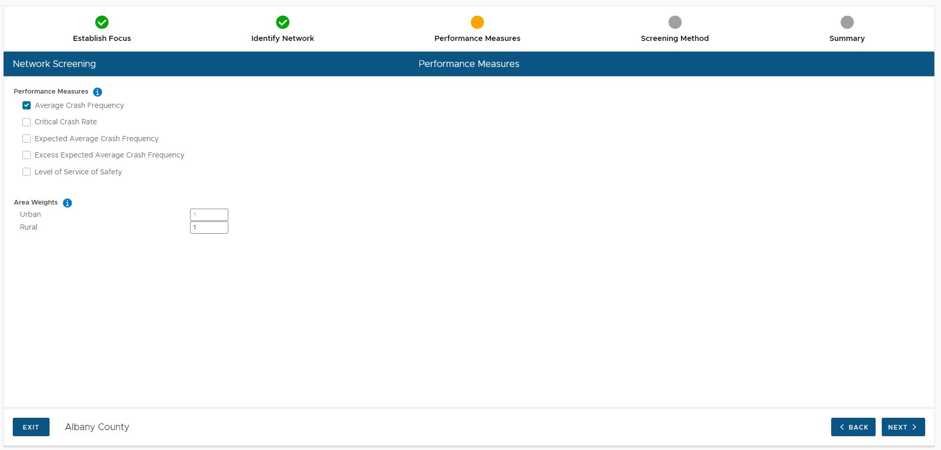
Check the boxes for the desired performance measures, and enter the desired weights for Urban and Rural areas, and click the NEXT > button to proceed to the next step.
Screening Method
The next step allows the user to select the screening method to be used as shown in the image below.
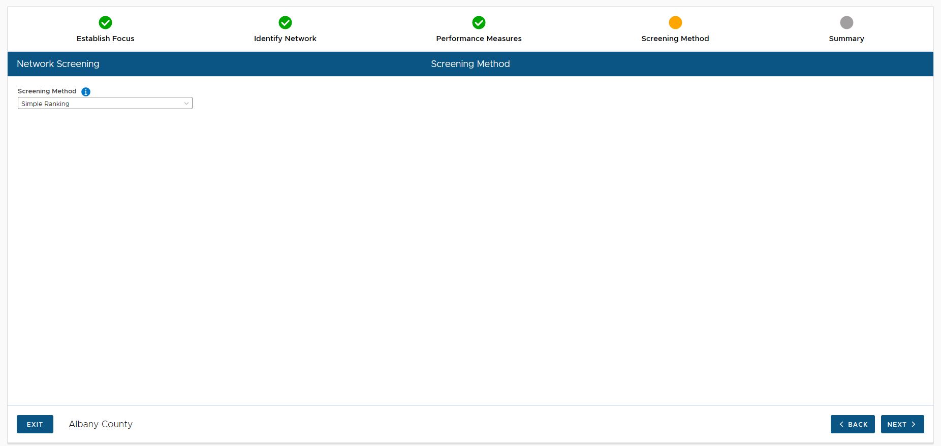
The two methods are as follow:
•Simple Ranking
•Best Available (Simple Ranking or Sliding Window)
Select the desired method from the picklist. Note: When best available is selected, the user is prompted to enter the window length and increment for when sliding window is used as shown below.
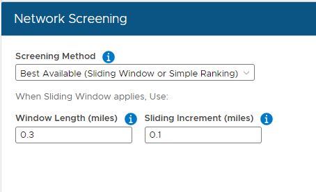
Specify the desired screening method and click the NEXT > button to proceed to the next step.
Summary
The final step in the Network Screening Scenario wizard presents a summary of the parameters specified for the scenario as shown in the image below.
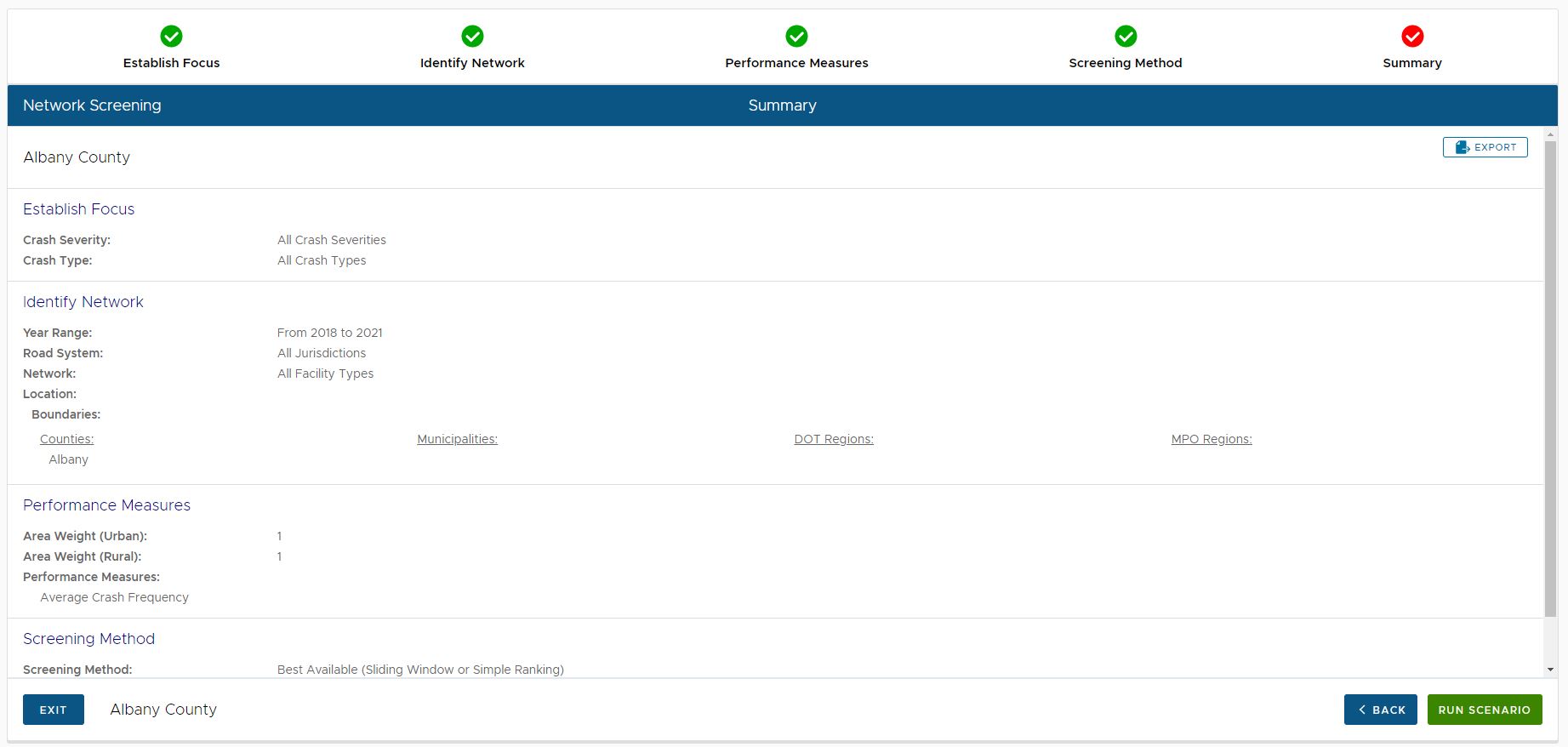
The user should review these parameters and if any incorrect, they should go back to a previous step to adjust the parameters.
The parameter summary displayed on the page can be exported to a PDF by clicking the EXPORT button in the upper right corner.
At this point the user can either click the EXIT button to exit the scenario without running it, or click the RUN SCENARIO button to execute the scenario.
Click the following link for details on viewing the results of a network screening run.
|